Bio Sensors: Difference between revisions
Jump to navigation
Jump to search
imported>Combuster No edit summary |
imported>Combuster m Fix the image and typos |
||
| Line 1: | Line 1: | ||
Recently started with some attempts regarding | Recently started with some attempts regarding bio-electrical sensors. | ||
After several failed attempts during OHM2013, finally something demonstrable: a | After several failed attempts during OHM2013, finally something demonstrable: a heartbeat monitor ([[Bio_Sensors#Version_1|Version 1]]). | ||
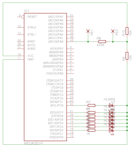
This setup measures voltage differences over two electrodes. The first one is wired up between two resistors to ground the system at half voltage relative to the other components, so we can measure voltage differences in both directions. The second electrode is separated from the first with a very high resistor so that it tends to middle voltage as well (and doesn't make the ADC drift). | This setup measures voltage differences over two electrodes. The first one is wired up between two resistors to ground the system at half voltage relative to the other components, so we can measure voltage differences in both directions. The second electrode is separated from the first with a very high resistor so that it tends to middle voltage as well (and doesn't make the ADC drift). | ||
| Line 7: | Line 7: | ||
=== Version 1 === | === Version 1 === | ||
[[ | [[File:ECG-version1.png]] | ||
<pre> | <pre> | ||
Revision as of 19:25, 10 September 2013
Recently started with some attempts regarding bio-electrical sensors.
After several failed attempts during OHM2013, finally something demonstrable: a heartbeat monitor (Version 1).
This setup measures voltage differences over two electrodes. The first one is wired up between two resistors to ground the system at half voltage relative to the other components, so we can measure voltage differences in both directions. The second electrode is separated from the first with a very high resistor so that it tends to middle voltage as well (and doesn't make the ADC drift).
Version 1
int sensorPin = A0;    // select the input pin for the potentiometer
int sensorValue = 0;  // variable to store the value coming from the sensor

void setup() {
  // declare the ledPin as an OUTPUT:
  for (int i = 2; i <= 8; i++)
  {
    pinMode(i, OUTPUT);
  }
}

void writebit(int pin, int value, int testbit)
{
    digitalWrite(pin, (testbit & value) ? HIGH : LOW);
}

void writebit2(int pin, int value, int testbit)
{
    digitalWrite(pin, (testbit > value) ? HIGH : LOW);
}

void loop() {

    sensorValue = analogRead(sensorPin) - 512;
    writebit2(8, sensorValue, -32);
    writebit2(7, sensorValue, -8);
    writebit2(6, sensorValue, -2);
    writebit2(5, sensorValue, 0);
    writebit2(4, sensorValue, 2);
    writebit2(3, sensorValue, 8);
    writebit2(2, sensorValue, 32);

    delay(10);
}
